Abstract
The latest significant developments in high angle conveyor technology, beginning in 1979, have led to the design of sandwich belt high angle conveyors which address a broad range of applications because they face few technical limitations in tonnage rate (exceeding 15,000 t/h), conveying angle (up to 90°), lift (approximately up to 107m (350 ft) with standard fabric belting and exceeding 305 m (1,000 ft) with steel cord or aramid fiber belting), etc. The present paper discusses the advantages of the sandwich belt concept, describes extensive testing (over a two-year period) of the latest sandwich belt high angle conveyors (HAC®), presents the latest HAC developments and identifies some of the many possible applications. Various applications in continuous ship loading/unloading, storage and transfer yard handling, midstream transfer and blending, elevation from underground hoppers and tunnels, preparation plants etc. demonstrate the versatility of the concept and the broad market potential.
Introduction
Development of the Sandwich Belt high angle conveyor concept has come a long way since its first introduction in the early 1950s. Over the approximate thirty year development period significant advances had been few and had come only in spurts. Such advances did not significantly build on past developments, rather they were independent developments which soon reached their technical limitations and did not develop further. The latest significant development of this technology, beginning in 1979, is the first to take a broad view of the industries to benefit from high angle conveyors, and of all significant developments to date. As a result, these latest developments know few technical limitations, address a broad market and offer a forum for further logical development or evolution. Significant speculatory advances in HAC technology were made and documented in a 1981 Bureau of Mines study (Ref 1). The more significant of these, with regard to past developments and the governing theory, were further discussed in a paper entitled “Evolution of Sandwich Belt High-Angle Conveyors” (Ref 2). The latest HAC developments, at Continental Conveyor USA, were further described and related to the governing theory in a writing entitled “Sandwich Belt High Angle Conveyors—HAC®, Evolution to Date” [3]. The significance of the latter writing is that it documents real, not speculatory, HAC® developments from the many engineering studies through the first large scale prototype into the first commercial units. HACs are now three years in successful operation. Further writings discuss HAC applications in open pit mining [4], storage and blending [5], and reveal the operational and economic advantages over the traditional haulage systems [1], [6]. The engineering studies prior to the HAC development conducted wide searches, in the literature and through industry contact, for the then state-of-the-art high angle conveying methods. Many methods were studied including skip hoists, bucket ladders, pocket belts, fin belts, cleated belts, sandwich belts, pipe belts, screw conveyors and others. Evaluation of all of the above revealed that nothing was available to meet the general needs of the mining and materials handling industries with regard to high volumetric conveying rates of non-homogenous materials, high lifts, adaptable conveyor profile, ease of operation and maintenance, and cost effectiveness. In depth study of the sandwich belt high angle conveyor technology at that time revealed much need for further development but offered much promise for success if such development adequately and thoroughly addressed the governing theory and constraints of conventional conveyor belt and component technology. The resulting high angle conveyors would fulfill the needs of the mining and materials handling industries and would offer the most operationally appropriate and most cost-effective solution. For comparison let us review some of the high angle conveying concepts available prior to the HAC® development.
Bucket Elevators
The two common types of industrial bucket elevators are classified according to the discharge method: centrifugal or gravity discharge type. Various discharge geometries may be employed in either case bur the discharge principle is either based on throwing (centrifugal) or dropping (gravity) the material into a discharge chute. The centrifugal discharge permits higher operating speeds (up to 2 m/s (400 FPM) in large bucket elevators) but is limited to elevating only loose, free flowing materials of uniform particle size. Materials of mixed size particles, moist materials, or any materials which flow sluggishly, can only be elevated at slower speeds (less than 1 m/s (200 FPM) even in large bucket elevators) to permit gravity discharge at the head end. Industrial pre-engineered elevators are available to approximately 200vh and to approximately 30.5m (100ft) of lift. High-capacity elevators can be engineered from standard buckets and chains or belts (depending on the chosen traction means) to approximately 1000t/h. Special girdle pocket elevators, made of draped belting reinforced to form rigid pockets, have also been developed for rates to 500t/h. Higher capacity bucket ladders, to 5000 t/h-coal, are used in continuous barge unloading machines. Hampered by the slow speed operation these tend to be massive elevating units, using 3m (10ft) wide steel buckets (of nearly 2t capacity) and high strength steel roller chains, and are suitable only for special purpose machines. The high capital cost and weight and the very high maintenance expenses make such bucket elevators inappropriate for general high angle conveying purposes.
Belt with Partitions
Belts with partitions compartmentise and contain the conveyed material between high profile transverse cleats. Two concepts of this type were investigated: the fin belt and the pocket belt. Fin belt The fin belt uses an ordinary flat rubber belt with three-part vulcanized rubber cleats across the belt, width, spaced along the belt length so that when the belt is troughed by three-roll carrying idlers, a barrier to material-slide back is formed. The fin belts have been in operation since 1961. They are recommended for handling mixed or coarse bulk materials and fines that do not tend to trickle. Belt speeds should not exceed 2 m/s (394 FPM) in order to avoid turbulence of the material at the loading point. Lower speeds are recommended when handling coarse materials. Pocket belt The pocket belt system has undergone considerable development since its first introduction to the industry and is manufactured by several belting companies around the world under different trade names. For high angle conveying, the system uses continuous corrugated rubber sideskirts, and rubber cross cleats, vulcanized to a flat rubber belt to form box compartments along the belt length to contain the material. The special skirt design permits continuous bending around pulleys without fatigue of the corrugations. Cross-rigidising of the flat belt minimizes dishing and reduces agitation of the conveyed material. The pocket belt represents an improvement over bucket elevators in reducing the system weight and the large maintenance costs inherent in the former. The pocket belt also offers a wide variety of conveying profiles permitting conformance to a wide variety of high angle conveying applications. Pocket belt installations of very high rates, exceeding 1000 t/h were not known to the writer in 1982 but the potential for high conveying rates was claimed. Typical operating speeds remained relatively low, below 2.5 m/s (500 FPM), even under controlled loading conditions. Cost estimates also indicated no significant reductions in capital cost compared to the high-capacity bucket elevators previously discussed.
Summary of Bucket Elevators and Belts with Partitions
The latter concepts offer significant reductions in weight and in maintenance costs and are more suitable for the high angle conveying function than the former. All of these concepts however share the following common shortfalls which led us to seek yet a better solution:
- Practical, or cost-effective high conveying rates are limited by low operating speeds.
- All concepts employ special, non-standard hardware. Such hardware is not typically available on short notice and tends to be more expensive due in part to limited sources of supply.
- Any concept with buckets or cross cleats cannot be continuously scraped. Sticky material cannot be completely discharged and is partially carried back along the return strand.
- The complications and obstructions do not permit easy and quick repair of the traction elements.
- With the latter two concepts, the conveying rate falls off as the conveying angle increases because the compartments can only be partially filled.
Sandwich Belt Concepts
The sandwich belt concept appeared to offer promise of a better solution for conveying materials at high angles, high speeds, high conveying rates and for achieving high lifts. Sandwich belt conveyors for general high angle applications were not well developed at the time-of our studies and the governing theory was not well understood. Shortcomings of past developments had led to abandonment of the concept for general purpose high angle conveying. Only two special purpose sandwich belt elevating concepts remained, and though severely limited for general use, these exhibited features which pointed to the great promise in the sandwich belt concept.
The Sandwich Belt Principle
The sandwich belt approach employs two, ordinary, rubber belts which sandwich the conveyed material between. Additional force on the belts provides hugging pressure to the conveyed material in order to develop sufficient friction at the material to belts and material to material interface so that sliding back will not occur at the design conveying angle.

Fig. 1: Idealized model 1 of Sandwich Belt conveyor

Fig. 2: Idealized model 2 of Sandwich Belt conveyor
Figure 1 is a simplified illustration of the interaction of forces. If the cover belt is not driven, then the lineal force N to provide the required hugging pressure at conveying angle a is given by the following equation:
![]()
where µ = µm or µ = µb, whichever is smaller.
A more realistic model is shown on Figure 2. An ample belt edge distance assures a sealed material package during operation even when belt misalignment occurs. A more comprehensive treatment of force interaction for a complex model along with the implications of driving both belts is not within the present scope and can be found in references 2 and 3.
Loop Belt and Beltavator
The remaining sandwich belt concepts at the time of the high angle conveying studies (beginning in 1979), the Loop Belt and Beltavator had been well developed by Stephens Adamson of Canada and were enjoying commercial success with many working installations.
Loop Belt The Loop Belt is a sandwich belt elevator of approximate semi-circular carrying profile from the loading to the discharge point. An inner belt loop is pressed against closely spaced troughing idlers throughout the convex curved profile by an outer belt loop. The outer belt is straight at the loading region and supported on troughing impact idlers. Idler support is discontinued before the outer belt joins the inner belt at the sandwich entrance. Throughout the vertical curve, the outer belt tension induces sufficient radial pressure on the curved profile to overcome the normal component of the belt and conveyed material weight and to hug the conveyed material so that it will not slide back. The sandwiched material thus loops around, approximately 155-180deg, to the discharge point. The Loop Belt has been successful in self-unloading ship applications and in several outdoor installations. It has achieved 10,000 t/h in elevating iron ore pellets and coal and lifts up to 45.7m (150ft). Typical belt speeds are comparable to conventional belt conveyor speeds, in the 4.1 to 6.1 M/s (800 to 1200 FPM) range. This concept uses all conventional belt conveyor components including smooth surfaced rubber belts. The severe drawback of the Loop Belt, in general high angle conveying applications, is the profile geometry which must always by approximately semi-circular. It cannot conform to conveying along with straight incline.
Beltavator The Beltavator is similar to the Loop Belt but introduces a straight vertical section to the profile. This makes it more versatile, permitting C, s, and L shape profiles. Angled inclines are not possible, however. Along the vertical elevating segment, the belt sandwich is held together by closely spaced, staggered-edge rolls which press the belt edges to keep the sandwiched material sealed between. Hugging pressure to develop the needed friction within the sandwich is derived from the prying resistance of the two belts as the material is introduced between them. The required transverse stiffness of the belts imposes capacity limitations on the Beltavator. As belt width requirements become large, at higher tonnage rates, increasingly stiffer and therefore thicker multi-ply fabric belts are needed. Practical belt widths are limited to approximately 941mm (36 inches), and maximum capacity is approximately 1,000 t/h when elevating dense material at high speed.
Summary of Loop Belt and Beltavator
These too did not offer the broad scope high angle conveying solution for the mining and materials handling industries because of poor profile conformity of the Loop Belt and inherent tonnage limitations of the Beltavator. These did demonstrate smooth running at high speeds with a variety of materials and demonstrated the for unlimited tonnage rates using conventional components and exploiting inherent characteristics of any conveying system (such as belt tension, transverse stiffness, etc).
Continental HACS
Though much development was needed, the sandwich belt concept clearly offered the greatest potential for a cost effective operationally appropriate high angle conveying system to address the broad scope needs of the mining and materials handling industries.
Following the extensive study of past sandwich belt conveyors, the governing theory and constraints and development of the governing design criteria, a broad scope effort was undertaken in 1982 at Continental Conveyor & Equipment Co Inc, USA, to develop the first sandwich belt high angle conveyor to meet these needs. Towards this end, many mine and terminal operators and planners were consulted at various stages of development.
The resulting HACs, described on Figures 3-11 and Tables 1, 2 and 3 are truly evolutionary in judiciously selecting and advancing past desirable features while omitting the non-desirable features. They are entirely conforming to the governing theory and constraint equations and to the development criteria.
| Table 1: High angle conveyor – HAC® test and demonstration prototype unit data | |
| Materials conveyed | Lignite, coal, copper ore and waste rock, iron ore pellets, sand, gravel, grain |
| Conveying angle | Variable from 30° to 60° |
| Design conveying rate at 60° angle | 1955, 2468, 2684, MTPH |
| (2155, 2721, 2959 STPH) | |
| Respectively for materials of density .8, 1.6, 2.4 mt/cum | |
| (50, 100, 150 PCF) | |
| Belt width | 1524 mm (60 in) |
| Belt speed | Infinitely variable from 0 to 6.1 m/s (0 to 1200 FPM) |
| Elevating height | Variable 7.9 to 19.5 m (26 to 64 ft) |
| Overall Conveyor Length | 35 m (115 ft) |
| HAC Conveyor Drives | |
| Top Belt | 74.6 kW (100 HP) |
| Bottom Belt | 111.8 kW (150 HP) |
The HAC fulfills all of the established operational requirements. HAC profiles can conform to a wide variety of applications. The HAC is well suited to a self-contained modular unit, utilizing nylon fabric belts to achieve short vertical radii of curvature, as it is to a single-run approach utilizing steel cord or aramid fibre belts requiring very large transition curves [3], [4].
Advantages of Sandwich Belt HACs
HACs can take on various profiles (Fig. 3) and offer many advantage [3], [4], [11] over other systems, including:
- simplicity of approach
- virtually no limitation in capacity
- high lifts and high conveying angles up to 90°
- flexibility in planning and in operation
- easy cleaning and quick repair of belts
- spillage-free operation
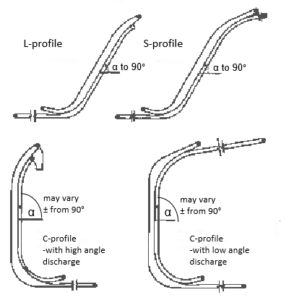
Fig 3: HACs with different profiles
| Table 2: Triton Coal Company high angle conveyor – HAC® data | |
| Materials conveyed | coal |
| Conveying angle | 60° |
| Conveying rate | |
| Design | 1814 mtph (2000 stph) |
| Surge | 1996 mtph (2200 stph) |
| Belt width | 1524 mm (60 in) |
| Belt speed | 4.65 m/s (915 fpm) |
| Elevating height | |
| Loading point to discharge | 32.9 m (108 ft) |
| Horizontal projection | |
| Loading point to sandwich entrance at 0° conveying angle | 32.9 m (108 ft) |
| Sandwich entrance at discharge | 25.6 m (84 ft) |
| Overall conveyor length | 56.7 m (186 ft) |
| HAC Conveyor drives: | |
| Top Belt | 112 kW (150 HP) |
| Bottom Belt | 149 kW (200 HP) |
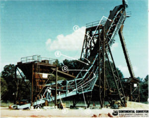
Fig 4: HAC prototype at 60 deg
| Table 3: High angle conveyor – HAC® for Majdanpek copper mine in Yugoslavia | |
| Materials conveyed | Copper ore |
| Density | 2.08 mt/m3 (130 PCF) |
| Lump size | 250 mm (10 in) max |
| Conveying angle | 35.5° |
| Conveying rate | 4000 mtph (4409 stph) |
| Belt width | 2000 mm (78.7 in) |
| Belt speed | 2.67 m/sec (525 fpm) |
| Elevating Height | 93.5 m (307 ft) |
| HAC Conveyor drives | |
| Top Belt | 450 kW (600 HP) |
| Bottom Belt | 2 x 450 – 900 kW (1200 HP) |
HAC® – INSTALLATIONS
HACs are now well into the commercial stage with the first commercial unit in operation since June 1984 (Fig. 5, Table 2). Two additional significant HACs have been delivered (Fig. 6, Table 3 and Fig. 7, Table 4) and engineering of the latest commercial unit (Fig. 8, Table 5) is presently under way.
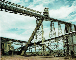
Fig 5: Triton Coal HAC, Western USA
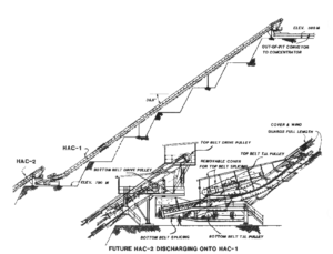
Fig 6: HAC at the Majdanpek copper mine, Yugoslavia
The first large scale HAC, however, began operation in June of 1983. It was at the 1524mm (60in) belt width prototype (see Fig. 4, Table 1) that a year long testing programme was conducted to verify the theory and develop specific design criteria. Because of the versatility built into this unit, including various incline angles from 30deg to 60deg and various belt speeds, it was possible to investigate the limits of the concept. The programme included large scale testing of basic material properties and their relation to conveying characteristics at the HAC at various conveying angles, speeds and degree of cross-sectional filling.
| Table 4: Data of HAC® for Western U.S. coal mine | |
| Material conveyed | Coal |
| Conveying angle | 35° |
| Conveying rate | 2,903 t(metric)/h |
| (3,200 short tons/h) | |
| Belt width | 1,829 mm (72 inch) |
| Belt speed | 4.57 m/s (900 ft/min) |
| Elevating height | 29.0 m (95 ft) |
| HAC conveyor drives | |
| – top belt | 149 kW (200 HP) |
| – bottom belt | 224 kW (300 HP) |
Materials tested included Texas lignite, Alabama coal (run of mine, lump, sized, sized and washed), Arizona and Tennessee copper ores, river run gravel, soybeans, iron ore pellets, and sandstone. Testing proved successful in all cases with all materials conveyed at various speeds to 60deg conveying angle. At the 60deg angle, demonstrated conveying rates exceeded 1814wh (metric) (2000t/h (short)) with coal and lignite, 2722t/h (metric) (3000Uh (short)) with copper ore, gravel, and sandstone, 51,000 bushels per hour (1795m7/hr) with soybeans, and 2812t/h (metric) (3100vh (short)) with iron ore pellets.
In addition, damage testing was performed on three USDA Grade 1 grains to demonstrate the gentle distribution of hugging pressure on the sandwiched material. Five one-bushel samples were loaded into oversized burlap sacks from each of a common batch of soybeans, wheat and seed corn. The first bushel of each grain was set aside to serve as the control sample while the next four bushels were conveyed at 60deg, the full length of the HAC prototype, two, four, six and eight times respectively for corresponding conveying distances of 45.7m (130ft), 91.4m (300ft), 137.2m (450ft) and 182.9m (600ft). Samples (2555g) from each bushel sack were then analyzed at a State of Alabama Department of Agriculture lab for the various forms of damage and contamination, and at the Alabama State Seed Laboratory Department of Agriculture and Industries for germination potential. The results showed no damage to any of the three grains tested, as a result of conveying in the HAC prototype.

Fig 7: HAC at Western U.S. coal mine
Conveying to 60° has proved very successful and indicates no limit on conveying angle to 90° (vertical). HACs are thus offered with conveying angles to 90°, as in the latest commercial unit (Fig. 8, Table 5). Success in testing and convincing demonstrations led to the sale of the first commercial HAC unit (main feature described in Table 2) to a western coal mining company in the latter part of 1983. The HAC permits a short direct path to the company’s train loading silos, rather than the long route through the blending silos, as previously required. The unit was commissioned in June of 1984 and has operated successfully to date. The second commercial HAC unit (main features described in Table 3 and illustrated in Fig. 6), was sold to a Yugoslavian copper company, and will be installed within a deep open pit copper mine. This HAC is part of an in-pit crushing and conveying system which incorporates in-pit trucking to portable crushers to an in-pit conveying system which feeds the HAC.
| Table 5: Data of HAC® for sludge, Eastern USA | |
| Material conveyed | sludge |
| Conveying angle | 90° |
| Conveying rate | 50 t(metric)/h |
| (55 short tons/h) | |
| Belt width | 610 mm (24 inch) |
| Belt speed | 1.40 m/s (275 ft/min) |
| Elevating height | 20.4 m (67 ft) |
| HAC conveyor drives | |
| – top belt | 11.2 kW (15 HP) |
| – bottom belt | 5.6 kW (7.5 HP) |
The HAC elevates the crushed ore from the pit onto an out-of-pit conveyor system to the coarse ore pile at the plant. The HAC unit incorporates many design features which make it especially suitable for elevating coarse copper ore from the deep open pit mine. It is designed to permit installation of a second future unit to elevate ore from a deeper pit location onto the tail of the first HAC. Only the most rugged conveyor components are used to insure smooth running in a very severe open pit mining environment. The modest 35.5deg conveying angle is limited by stability of the mine slope.
Broad Horizons
This writing thus far has rationalized the need for developing sandwich belt high angle conveyors and has described the successful development of HAC®s into the present stage of commercialization. It has also described the versatility of HACs with regard to profile, and the appropriateness for the broad needs of mining and materials handling applications.
Previous writings have pointed out the many possible open pit mining applications [1], [4], [6]. It is the primary purpose of this writing to identify some of the many possible additional HAC® applications in continuous ship loading and unloading, storage and transfer yard handling, midstream transfer and blending, elevation from underground hoppers and tunnels, and prep plant applications.
Continuous Ship Loading
Traditional ship loaders are typically rail mounted travelling machines supported on a long dock structure. These machines are provided with a loading conveyor boom which continuously discharges material through a loading chute into the hold of the ship. The boom can typically alter its luffing angle during operation and to a non-operating storage position. Depending on specific requirements and or design preference, the boom may be of the shuttling or of the slewing type. In either case these features permit positioning of the loading chute where desired in the ship’s hold. Further possible features include articulating and or telescoping chutes with or without material flingers to trim the ship’s hold for complete filling.
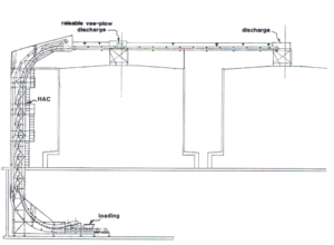
Fig 8: C-profile HAC for sludge, Eastern USA
A dock conveyor must feed the material to the boom belt via a tipper. The dock length must therefore be determined for the travel range of the ship loader plus the tripper length. Tripper length can often add 100m (328ft) or more to the dock length depending on the operating belt tension and height of the boom loading point. This consideration has in many cases led to elevating the entire dock belt thus shortening the tripper length. The correct solution is a question of economics, trading extra dock length for support structure at the elevated dock belt. The linear shiploader design is a notable exception to the above description and was, in part, developed in response to these considerations. Fig. 9 illustrates yet another solution using a C-profile HAC as an elevating belt from the discharge of a short tripper to the loading point of the ship loading boom. This solution minimizes the required dock length without the need to elevate the entire dock conveyor. Dock length savings in the 30m to 60m (98ft to 196ft) range can reduce dock costs approximately US $1,000.000 to $2,000,000 (based on $10,000 per foot for a particular 16.5m (54ft) wide dock) depending on the dock design. Savings of $100,000 to $200,000 are also estimated at the shiploader with tripper. Fig. 10 and 11 illustrate a shiploader with loading HACs of S-profile. Often friable or damage prone materials such as coke, grains, etc must be lowered gently into a ship’s hold to minimize degradation from impact. When allowed to free fall through a chute the material grade may be appreciably lowered thus reducing the commodity’s selling price. The lowering HACs of Figures 13 and 14 offer solutions to this problem since it is possible to select any desired lowering speed.

Fig 9: HAC elevating to shiploader
With other materials which are not damage sensitive the lowering HAC of Figure 14 can be operated at high belt speed to fling the material evenly around the ship’s hold. This permits efficient filling of the hold as the material level approaches the combing.
CONTINUOUS SHIP UNLOADING
Continuous ship unloading equipment may be dock-based thus capable of unloading many conventional bulk carriers (Fig. 12) or it may be provided at each ship making it a continuous self-unloader (Fig. 13). The choice depends on many factors including unloading rate, haul distance, port draft etc.
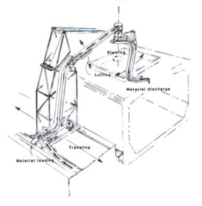
Fig 11: HAC shiploader at low speed – similar to Fig 10, but with more versatility at high speed, loading and trimming by flinging material around the entire area of the ship’s hold.
Dock based continuous ship unloaders—CSUs were the focus of much attention in the early to mid-1970s. The transhipment of bulk materials was growing and projected to grow at alarming rates along with the size of bulk carriers, beyond the 350,000dwt class. Clamshell unloading rates to approximately 1200t h were thought to be a practical limit, for the concept, while continuous unloaders were thought capable of much higher unloading rates. This was important since the time spent at port was extremely costly for the large bulk carriers. Early high-capacity CSU concepts centered on the chain mounted bucket ladder for the digging and elevating duties. Hampered by the required ruggedness of the digging duty and the limited chain speed to approximately 400 FPM with free-flowing materials; CSU unloading booms and thus the entire machine became massive beyond the original projections. The cost of dock structures to carry these machines also increased. In the face of these technical problems along with revised, less ambitious. projections for transhipment of bulk materials, the focus on large capacity CSUs diminished. Instead, the interest shifted to lower capacity CSUs comparable in unloading rate to the clamshell unloaders.
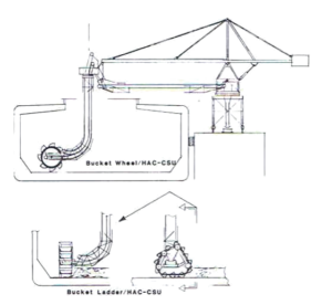
Fig 12: Continuous ship unloaders – bucket wheel/HAC-CSU and bucket ladder/HAC-CSU
Various designs emerged, from all bucket elevating systems to screw type elevators, to designs which separated the digging and elevating functions. The latter combine bucket wheels with pocket belts or light duty bucket elevators, and augers with air pressed sandwich belts. HACs because of the favourable features previously described, make possible CSUs of virtually unlimited capacity and suitable for a wide range of materials. Separation of the digging and elevating functions as indicated in Fig. 12 permits high speed operation of the L-profile HAC, minimizing the cantilevered weight and thus the entire machine weights. The concept with short bucket ladder digging means is expected to permit better cleanup of the hold and to be more tolerant of wave action because the sagging chain is in partial suspension as it drags the ship’s bottom. Self-unloading ships have gained prominence in the last decade because of their high unloading rates, exceeding 10,000t h, because they need no expensive unloading facilities at the unloading docks and because of their ability to load or top off larger bulk carriers at sea. The last feature is especially important for export shipments when the loaded draft of the export carrier exceeds the water depth of the loading ports. HACs of C-profile with high angle discharge are especially adaptable to self-unloading ship applications because of unlimited tonnage capacity at high belt speed, suitability for a wide variety of materials, and a vertical elevating profile which minimizes space requirements.

Fig 13: Self-unloading ship with HAC system
MATERIALS HANDLING YARDS
HACs offer savings in structure and in real estate in a wide variety of transfer yard applications. Figure 14 illustrates savings in yard length and tripper (estimated in the range of $100,000 to $200,000) when a C-profile HAC is used to elevate material to the boom of a stacker or stacker reclaimer. The arrangement shown is equally suitable for stacker/reclaimer operation with reversing or through type yard belt. The latter need only incorporate a bifurcated chute with flop gate, at the tipper discharge, able to direct material flow to the HAC or alternately back onto the yard belt.
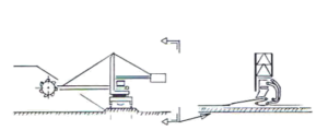
Fig. 14: Stacker/reclaimer with elevating HAC – yard belts may be through-type or reversible
ELEVATING FROM UNGROUND
HACSs offer potential for large savings in tunneling costs when used to elevate materials from underground. Figs. 15 and 16 illustrate just two of many possible applications: A conventional conveyor at modest incline, to approximately 15°, is presently the most popular means for elevating large tonnages continuously from underground. A 60m (197ft) lift thus requires 232m (761ft) of 15° slope conveyor and tunnelling. Use of the HAC as the elevating means retains all of the positive features of a conventional conveyor while requiring only a 60m (197ft large diameter vertical shaft. Considering the technological breakthroughs in large diameter vertical shaft boring, the savings in tunnelling costs can exceed US$1,500,000 for this sample case. Furthermore, vertical shafts tend to be less prone to wall or roof collapse.
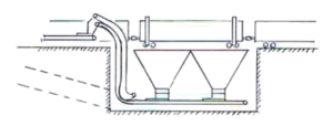
Fig 15: HAC elevating material from under dump hoppers
Fig. 15 illustrates a case where the slope tunnel is not necessary when the HAC is used to elevate from under dump hoppers. All conveying and elevating equipment remains within the confines of the dump vault.
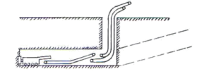
Fig 16: HAC elevating from underground excavation projects such as underground mines, tunneling, deep foundations and caisson, underground storage tanks etc.
CRUSHING, BLENDING, WASHING AND SAMPLING
In the beneficiation of bulk commodities, materials must be elevated to the top of crushing, sampling, washing towers, blending silos, etc. Gravity usually returns the material to the next loading point where it is again elevated. Complex beneficiation systems are needed at metal and non-metal mines, coal mines, prep plants, smelters, mills, power plants, grain terminals, etc. Beneficiation systems are predominantly land based as in Fig.17 but can also be mounted on large floating platforms as depicted by the midstream terminal of Fig. 18.

Fig 17: HAC at land-based beneficiation system to elevate between various stages of crushing, blending, sampling, washing etc.

Fig 18: HAC at barge-to-ship floating transfer terminal, to elevate between various stages of blending, sampling etc and to the shiploader
Elevating to the various stages has been traditionally by conventional conveyors and when space is limited by bucket elevators and skip hoists. HACs offer all of the positive features of conventional conveyors without the profile limitations. High tonnage rates at the least capital, operating and maintenance costs are possible with HACs, and with a minimum space.
MIDSTREAM TERMINALS
For reasons cited in the earlier discussion of self-unloaders, midstream terminals have also been the focus of much attention in the past five years. The grain companies have led the way in this effort, building several terminals for operation in the lower Mississippi River and Gulf of Mexico. USA, and at Europort-Rotterdam. These have incorporated continuous unloading of river barges by bucket ladder. blending and sampling systems by combined use of conveyors and large bucket elevators and ship loading by a slewing conveyor boom. The coal industry has also developed barge to ship midstream terminals, mainly for topping off large export bulk carriers in the Gulf of Mexico, USA. These have consisted of pontoon mounted grab cranes which transfer material directly from barge to ship with each grab cycle. Because of the previously cited technical limitations unloading rates are modest even with several grab cranes. In either grain or coal or other Applications, HACs facilitate midstream operations at the highest throughput rates within the least space.
SUMMARY AND CONCLUSIONS
This and previous papers have described the broad-scope effort at Continental Conveyor, USA, which led to the development of the Continental high angle conveyor – the HAC® – in 1983. Previous papers focused on HAC systems for open pit mining. It has been the main purpose of this paper to describe HAC systems for a wide range of materials handling applications, thus illustrating the versatility of the concept. Review of the commerical installations to date yields the best evidence of the HAC®s great versatility, varying in profile from S- to L- to C-shape (Figs. 4 to 8), in elevating angle from 30° to 90°, in materials handled from coal, to coarse ore, to sludge, and in throughput rate from 50 to 4,000 t(metric)/h. Because of the HAC’s great versatility and proven performance, its advantages may now be exploited with confidence in a wide variety of applications, especially those described in this paper.
REFERENCES
[1] E A. Siminerio, A C and Dos Santos, J A. High Angle Conveyor Study by Dravo Corporation for Bureau of Mines. US Department of the Interior under BuMines Contract No. J0295002, 1981, Vol.I, 291 pages, Vol.II. 276 pages. [2] Dos Santos, J A and Frizzell, EM. Evolution of Sandwich Belt High-Angle Conveyors, CIM Bulletin, Vol.$76, Issue 855. July 1983, pp. 31-66. [3] Dos Santos, J.A.: Sandwich Belt High Angle Conveyors – HAC® – Evolution to Date; bulk solids handling Vol. 6 (1986) No. 2, pp. 299-314 [4] Dos Santos, J.A.: Sandwich Belt High Angle Conveyors – Applications in Open Pit Mining; bulk solids handling Vol. 4 (1984) No. 1, pp. 67-77. [5] Mitchell, J J. High Angle Conveyors Climb to the Top Coal Mining, November 1984 Issue. Maclean Hunter Publication Chicago USA, pp. 39-43. [6] Michell, J J and Albertson, DW: High Angle Conveyor offers Mine Haulage Savings, BeltCon 3 International Materials Handling Conference 9, 10 and 11 September 1985, Landdrest Hotel Johannesburg, South Africa. [7] Stephens-Adamson. The Stephens-Adamson Loop Belt Elevator, Belleville, Ontario, Advertisement. [9] Loop Belt to be Installed in Port Cartier, Engineering and Mining Journal, February 1977, p. 114. [10] Beltavator. Advertisement, Stephens-Adamson, Belleville, Ontario,Canada [11] Dos Santos, J.A., and Z. Stanisic: In-Pit Crushing and High Angle Conveying in Yugoslavian Copper Mine. Mining Latin America, Int. Mining Convention, Nov. 17-21, 1986, Santiago, Chile.
- Presented at CoalTrans ‘86, Amsterdam, The Netherlands, June 10-12, 1986, published in proceedings
- Published in Bulk Solids Handling, Vol. 7 (No. 2), April 1987, pp. 229-239
Recent Comments